
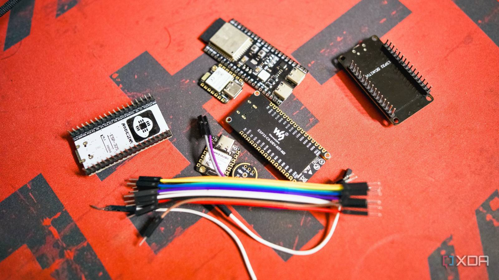
Published Sep 28, 2026, 11:00 AM EDT Samir Makwana is a technology journalist and editor from India since past 18 years and his work appears on MakeUseOf, HowToGeek, GSMArena, BGR, GuidingTech, The Inquisitr, TechInAsia, TechWiser, and others. He has written news, features, and gadget reviews for national technology media publications. His passion is to help people with their technology problems and gadget purchases. For that, he has worked for some of the biggest international technology publications, covering news, explainers, how-to guides, listicles, and product-buying guides. He has worked as an editor and managed teams since 2015. His expertise broadly covers computers, smartphones, game consoles, headphones, smart home products, browsers, and apps. A bunch of ESP32-based projects I’ve stumbled across on GitHub mention only a specific board, not which GPIO to use to wire a sensor. So even if I manage to get a similar ESP32 board and figure out the code, plugging the wires into the right pins is still a task. I prefer using DuPont jumper cables and ensuring the project code works properly. Typically, I’d choose the same GPIO number on an ESP32-based board and always struggle to get anything to work. But when I learned there’s more than one ESP32 and the differences between them, I stopped repeating the mistake and started following a fix, which always works. The ESP32 chip comes in a variety of distinct boards Each one exposes a different set of pins, headers, and flashing chips The ESP32 is the name of the chip, not the board. It’s not a single product with one fixed layout; it comes soldered onto different boards with different layouts. The DOIT ESP32 DevKit V1 board I have exposes 38 pins in a wide double-header. Meanwhile, the Waveshare ESP32-C6-WROOM-1-N16 board exposes 36 pins in a similar fashion. The tiny Seeed Studio XIAO ESP32-C6 mini breakout board exposes 14 pins. That’s just three boards, and one of them, the XIAO, doesn’t even ship with headers soldered on. So, wiring a sensor looks different before you’d picked up a single jumper cable. When my projects failed, even with the code fine, I figured the problem lay in the pins I chose. After scouring forums and Reddit posts, I learned that GPIO12 isn’t exactly the universal pin for all projects. It’s a strapping pin whose electrical level is checked at boot or reset to determine startup configuration. Even the flashing process can differ. Some boards use a CP2102 USB-to-serial chip, others a CH340, and that choice alone can affect which pins are usable while flashing, on top of whatever the strapping pins are already doing. That’s why, even though two boards can say ESP32, they still aren't interchangeable. GPIO numbers and the silkscreen labels don’t always match A marked pin on the board can point to a totally different GPIO number Some of the ESP32-based board makers label raw GPIO numbers next to each pin. Meanwhile, beginner-focused generic or custom development boards use D-number pin labels with no GPIO cross-reference. Those D-numbers are silkscreened to maintain compatibility with Arduino pins. That’s the kind of confusion that a few people have posted about on Espressif forums. While making a music-controlled RGB LED, I spent hours trying to make the circuit work consistently. That didn’t work because I kept picking the D15 on the development board, which turned out to be GPIO15, a critical strapping pin. The fix is a boring one, and it’s not smarter code. Every time I work on an ESP32 project, I pull up a pinout diagram for the exact board model to identify the correct GPIO and avoid the strapping pins. That means matching the silkscreen label on the board with the actual GPIO number. A few pins are critical on every ESP32 Those pins behave the same on every board After a series of failures to get the project working, I’ve finally memorized five strapping pins that are consistent regardless of the board: GPIO0, GPIO2, GPIO5, GPIO12, and GPIO15. The ESP32 chip checks these pins to decide the boot mode and flash voltage at every boot or reset. Pull one high or low with an external component, and you can change how the chip boots or stop it from booting altogether. That’s what happened with the microphone I was using with a music-controlled RGB LED. I struggled to connect the INMP441 microphone to a NodeMCU-32S board with the classic ESP32. I kept wiring the INMP441’s SCLK or WS pin to the wrong pins on the ESP32 board and eventually learned that GPIO34 to GPIO39 are input-only. That turned one of them into an antenna that picked up random electrical noise and caused it to read garbage data. Those input-only pins are true for every classic ESP32, and I'd assumed they were safe because they worked on someone else's board. Newer ESP32 variants don’t play by the same pin rules Shifting strapping pins, USB pins, and pin counts under the same name When I moved from classic ESP32-based boards to newer variants like the ESP32-C3 or ESP32-S3, I stopped mimicking old pin-picking habits. The C3 and S3 aren’t just different boards carrying the same ESP32 chip; they’re different chips, with their own strapping pins and pin counts. On the ESP32-S3, GPIO0, GPIO45, and GPIO46 handle the strapping duties, which are totally different from the classic ESP32. Also, GPIO19 and GPIO20 handle the native USB on the boards. That’s why using tutorials meant for classic ESP32 boards on a C3, S3, or a newer variant can quietly break the boot or reset sequence, even when the code remains the same. Find the board’s datasheet before soldering a wire No matter what project I’m picking next, I always apply one boring fix: find the board’s exact model number and pull up its datasheet or pinout diagram. ESPConnect is a self-hostable tool that lets you connect a microcontroller board over USB and reports exact chip variants, silicon revision, and flash size. That’s enough to know whether you’re holding a classic ESP32 or a newer variant, even if it can't tell you the vendor’s board name. Using that model number, I can search for the pinout diagram or datasheet, since most reputable board vendors publish them. That music-controlled RGB LED, the project that started this whole habit, has been running off GPIO4 for months now without a single reset loop. Brand AITRIP Connectivity Features UART, USB
ESP32 boards expose different pins, and using the wrong one silently breaks your project
Full Article
Original Source
Read the full article at Xda-developers →KhanList aggregates and links to publicly available news content. We do not host full articles from third-party sources. Always verify important information with original sources.