
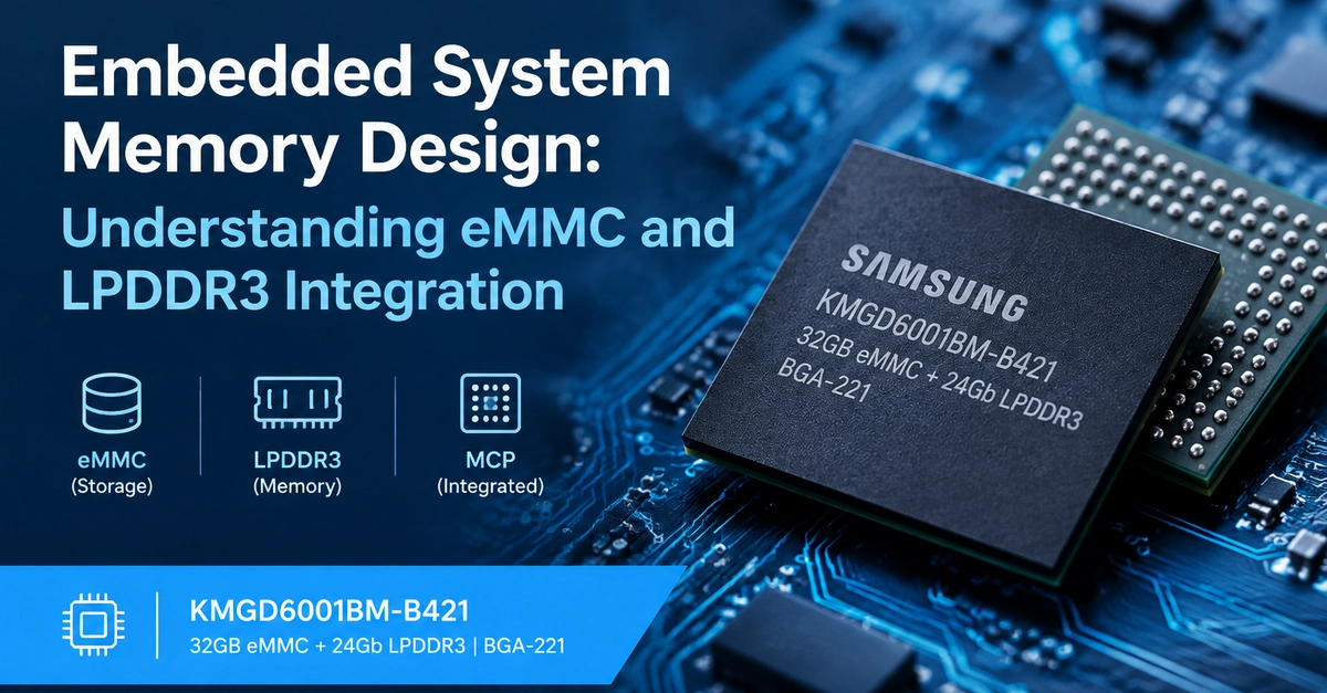
When designing an embedded system, choosing the right memory architecture is an important part of balancing storage capacity, performance, PCB space, power consumption, and overall system cost. For devices such as industrial controllers, connected equipment, multimedia platforms, and other embedded products, engineers often need to consider two distinct memory requirements: non-volatile storage for firmware and application data, and volatile memory for runtime operations. This is where understanding eMMC and LPDDR3 integration becomes useful. 1. eMMC vs. LPDDR3: What Is the Difference? Although eMMC and LPDDR3 can be used within the same embedded platform, they serve different purposes. eMMC (embedded MultiMediaCard) provides non-volatile storage. It can retain firmware, operating system files, configuration data, and application resources when the system is powered off. LPDDR3 (Low Power Double Data Rate 3) is volatile memory designed to support active processing workloads. It can be used for temporary data, working buffers, and runtime operations that require fast access to system memory. A typical embedded architecture may use eMMC for persistent storage and LPDDR3 for working memory. The processor manages data transfers between storage and RAM according to the software and system architecture. Understanding this distinction helps engineers evaluate memory requirements before selecting specific components. 2. What Is MCP Memory Integration? Multi-Chip Package (MCP) technology combines multiple semiconductor dies within a single package. For embedded designs, this approach can reduce the number of individual memory packages required on a PCB. One example is the Samsung KMGD6001BM-B421, an MCP memory device that combines 32GB eMMC storage with 24Gb LPDDR3 memory in a BGA-221 package. Engineers researching this component can review the KMGD6001BM-B421 product specifications and datasheet resources on Jotrin as a starting point for their component evaluation. Integrating storage and RAM into one package may help simplify board-level component placement. However, the actual benefits depend on the processor, memory interface, PCB layout, thermal conditions, and application requirements. 3. Key Factors to Check Before Selecting a Memory Component A component's capacity and package type are only the starting points. A thorough evaluation should cover several additional factors. Memory capacity Estimate how much persistent storage the operating system, firmware, applications, logs, and future updates will require. For RAM, consider the operating system's baseline consumption, application working sets, buffers, and peak concurrent workloads. It is also important to distinguish between GB and Gb: storage capacity is commonly expressed in bytes, while semiconductor memory densities are often specified in bits. Interface compatibility Verify that the target processor supports the memory technologies and interfaces required by the selected component. For an MCP device, check the relevant eMMC specifications, LPDDR3 interface requirements, supported bus widths, and controller capabilities against the manufacturer's documentation. **Package and PCB layout **A BGA package can support a compact design, but it introduces layout and assembly considerations. Review the package drawing, ball assignment, PCB footprint, routing requirements, power distribution, and assembly process before finalizing the board design. Power and thermal behavior Memory power consumption varies with operating conditions, data traffic, refresh activity, and device configuration. Review the applicable electrical specifications and operating limits rather than assuming that package integration automatically reduces power consumption. Lifecycle and supply continuity For products intended for long service periods, verify the component's lifecycle status, sourcing options, traceability requirements, and availability before committing to a production design. A suitable memory component must meet both the technical requirements and the project's supply-chain constraints. 4. Why Datasheet Verification Matters Part numbers that look similar can differ in memory organization, package configuration, voltage requirements, or timing characteristics. Before approving a component, engineers should verify: Exact manufacturer part number and revision eMMC capacity and supported operating modes LPDDR3 density, organization, and interface requirements Package dimensions and ball map Supply voltages and timing specifications Recommended operating conditions Compatibility with the processor and board design For the KMGD6001BM-B421, use the manufacturer's datasheet as the primary technical reference and cross-check the distributor's listing against the original documentation. A distributor product page can be a useful starting point for locating part information, comparing sourcing options, and requesting additional commercial details. Technical approval should still be based on the official component documentation. 5. A Practical Memory Selection Workflow For an embedded hardware project, a straightforward selection process can reduce avoidable design changes. Define the workload. Identify the operating system, application requirements, persistent data needs, and peak RAM consumption. Choose the memory architecture. Decide whether separate storage and RAM devices or an integrated MCP solution better fit the design. Check processor compatibility. Confirm supported memory interfaces, densities, bus widths, and operating modes. Review the datasheet. Validate electrical, timing, package, and environmental requirements. Build and test a prototype. Evaluate boot behavior, memory initialization, data integrity, workload performance, and thermal characteristics. Validate the supply chain. Confirm exact part-number identity, sourcing documentation, production requirements, and long-term availability. Following these steps helps connect component selection with real system requirements instead of relying on capacity or package size alone. Conclusion Memory selection is a system-level engineering decision. eMMC provides persistent storage, while LPDDR3 supports runtime memory needs. MCP technology brings these functions together in a single package, potentially helping engineers manage PCB space and component count. The Samsung KMGD6001BM-B421 is one example of this approach, combining 32GB eMMC with 24Gb LPDDR3 in a BGA-221 package. Whether you are developing a new embedded platform or maintaining an existing design, always verify the exact part number, interface compatibility, electrical requirements, and lifecycle information before making a final component decision. What factors matter most in your embedded memory selection process: capacity, PCB space, power consumption, interface compatibility, or long-term component availability?
Embedded System Memory Design: Understanding eMMC and LPDDR3 Integration
Full Article
Original Source
Read the full article at Dev →KhanList aggregates and links to publicly available news content. We do not host full articles from third-party sources. Always verify important information with original sources.